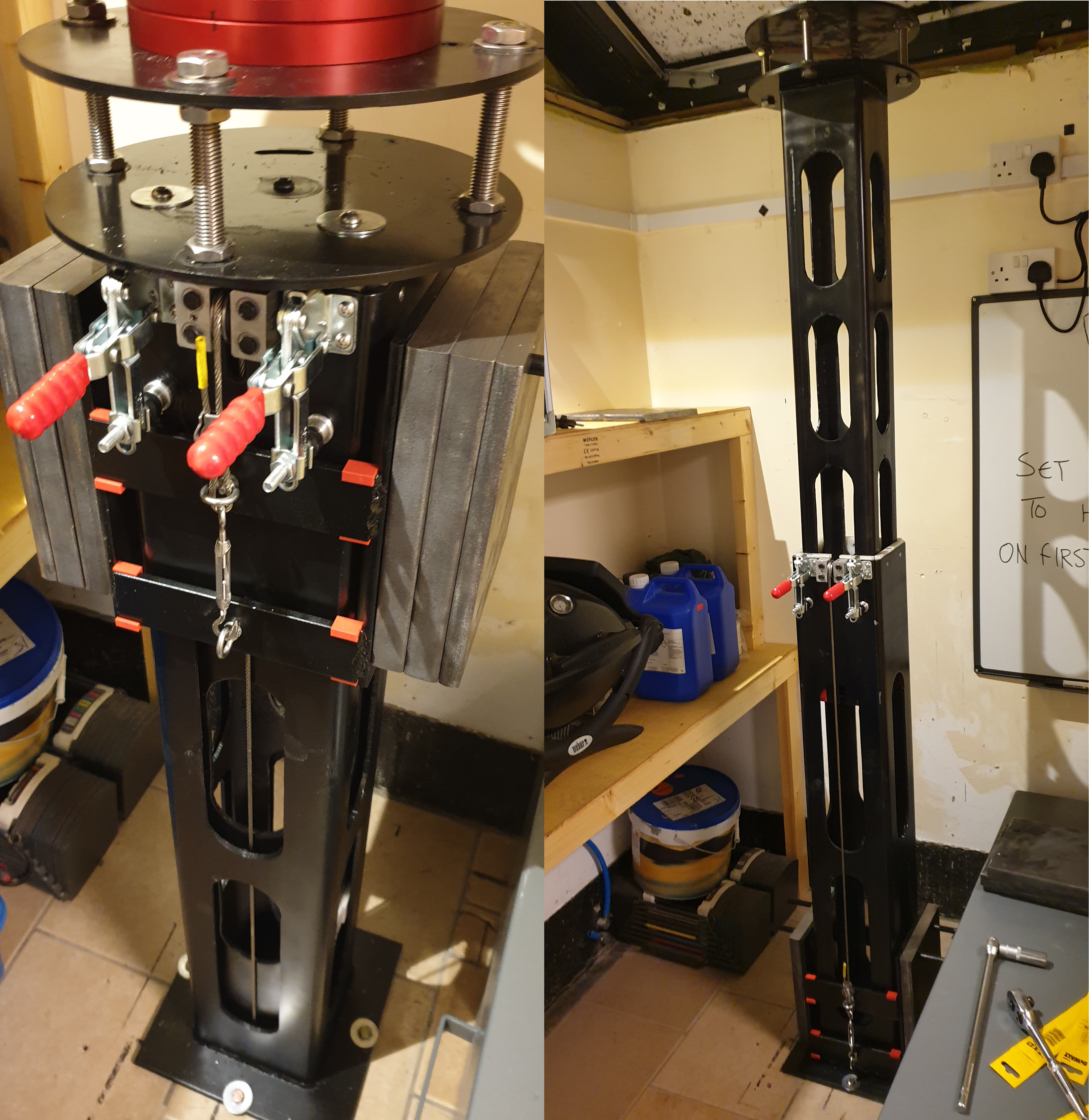
To give this some context my observatory has an opening in the roof rather than a entire slide off roof. The upshot of this is that my mount has to be lifted out of / into the roof to achieve this I have done a little bit of plasma cutting and a bit of welding to create a telescopic pier. This pier has a sled that travels up and down carrying counter weights so the mount / telescope are at neutral balance so I can lift them with one finger. The left image below shows the pier with the mount on when down the right image shows the pier up with mount / scope removed as the roof was closed.
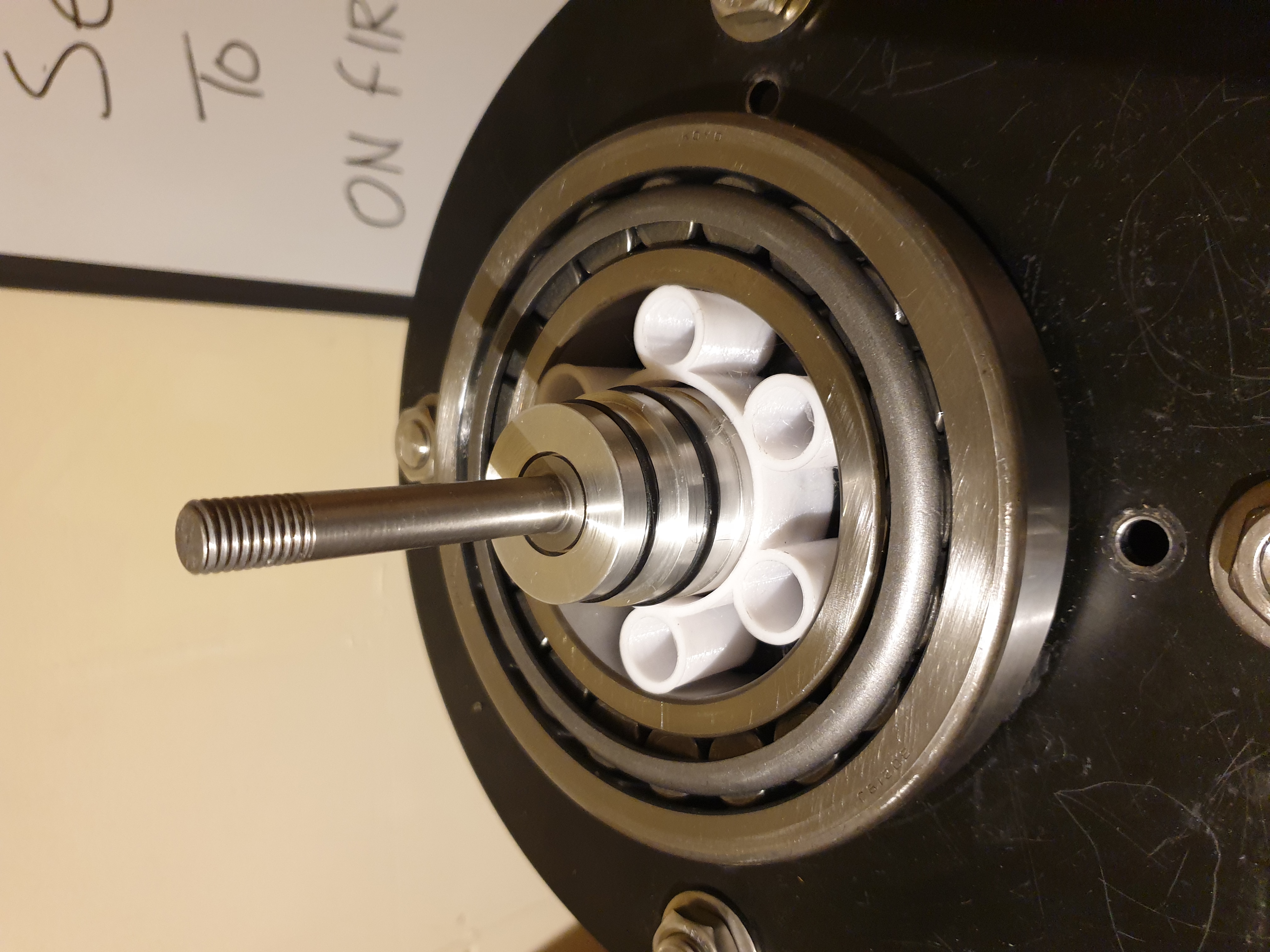
The upshot of this is that I have to stand on the security box to polar align then go back to the other room to check and then come back adjust and repeat until aligned. To resolve this I am building stepper controls to move horizontal and elevation on the mount. To achieve the left right movement I have machined a centre puck and shaft that allows the mount to be bolted to a 170mm taper roller bearing as in the image below.
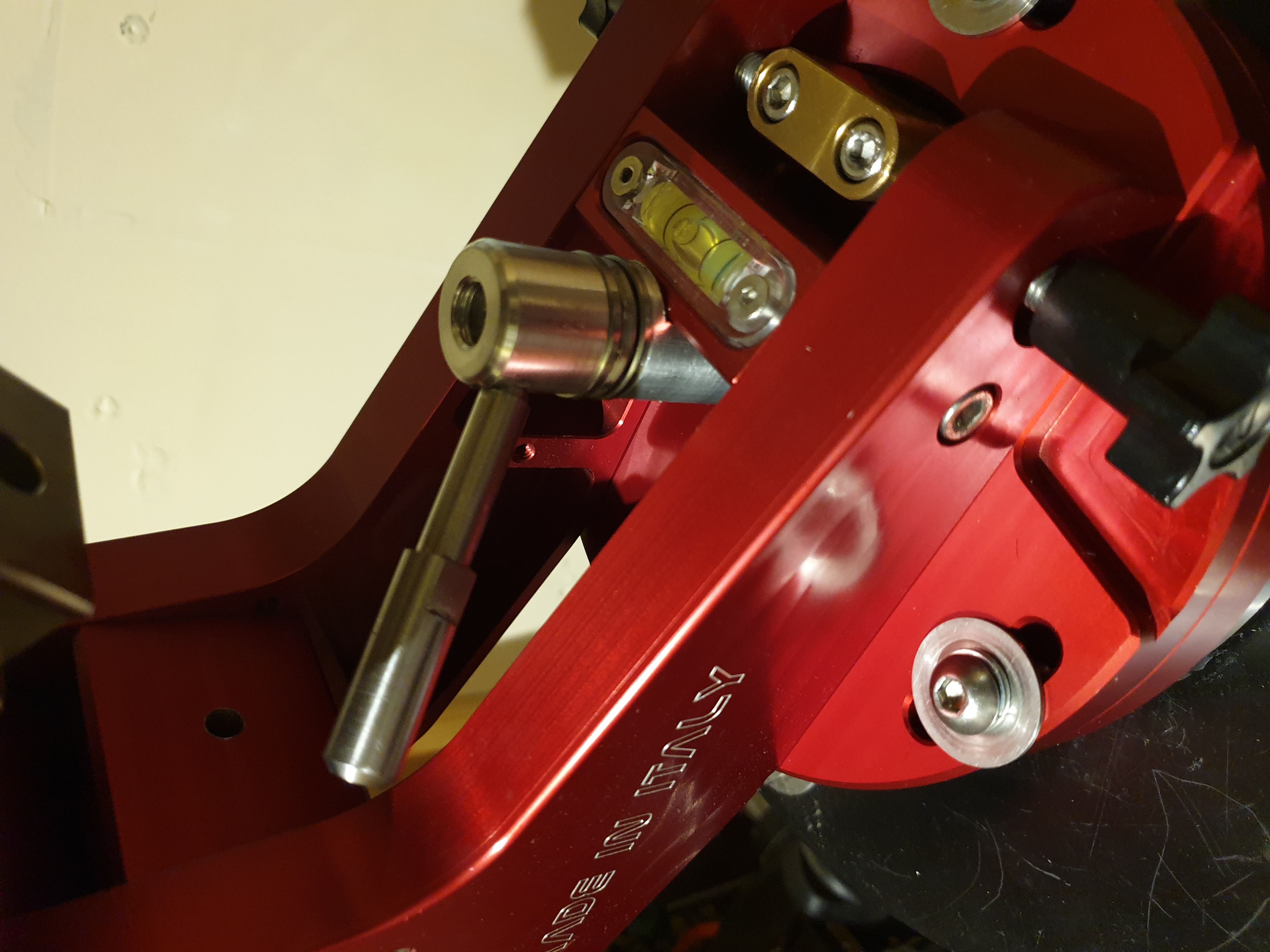
The mount is then secured to this and aligned by the centre puck so that it rotates on the centre axis. The mount is secured via the shaft a machined spacer thrust bearing and machine locking nut / handle. Will clean these up and do a bit of anodising when I get chance as seen in the image below. the left right polar alignment is locked out as the whole mount now rotates on the taper bearing.
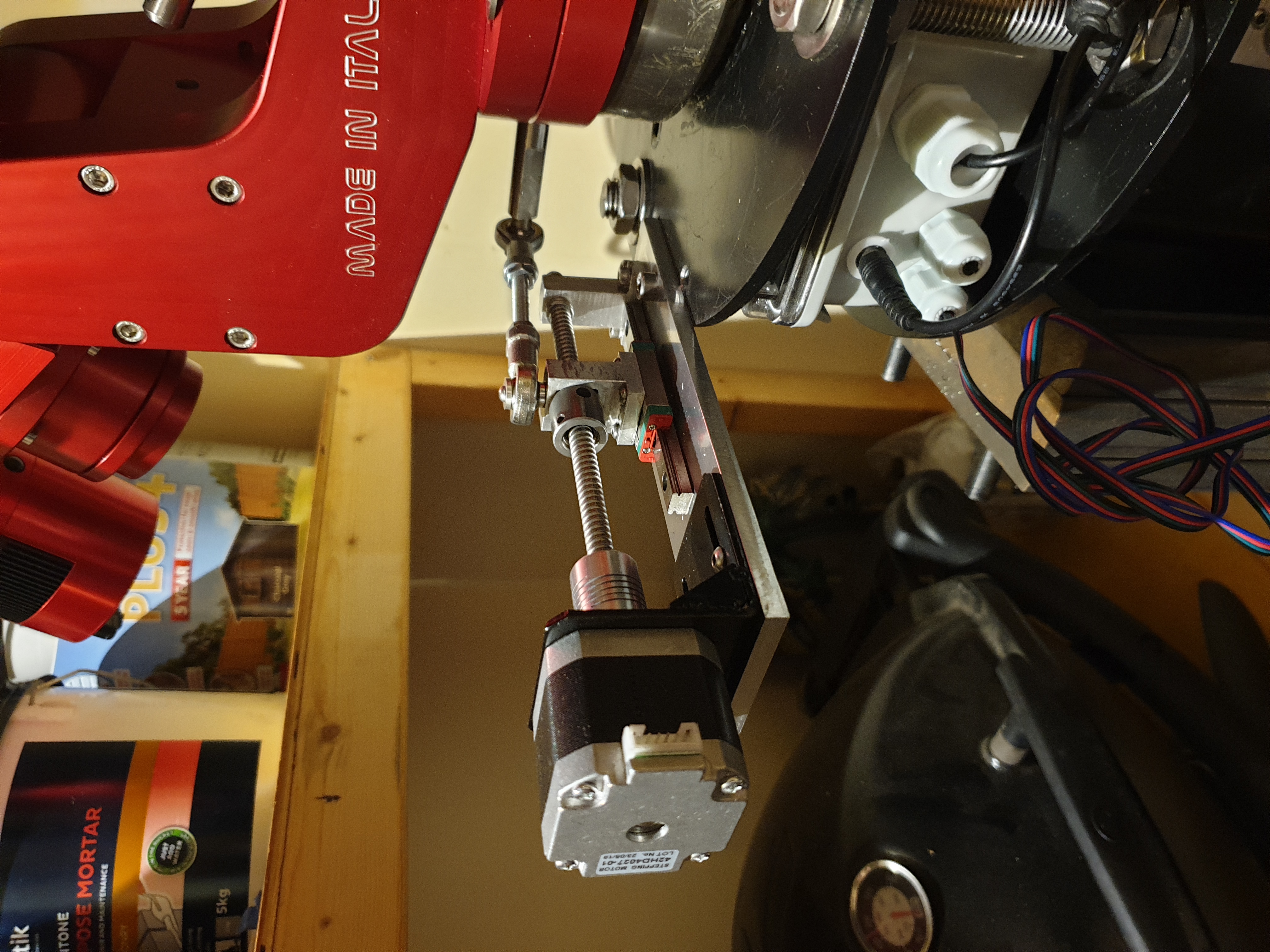
The reason for the bearing is that I can now use a stepper motor to drive a 3mm pitch ball screw at 3200 steps per revolution this is linked to the mount on a post at the rear roughly 140mm radius from the rotation centre so roughly 440mm in circumference so 1 degree of movement is 1.22 mm of travel on the screw so I can theoretically move the mount by 1/1300 of a degree when aligning. The image below shows the current stepper screw / link arrangement although at some point I will machine a new thread and carrier assemble as I only really need a short amount of actual travel so can make the unit much shorter.
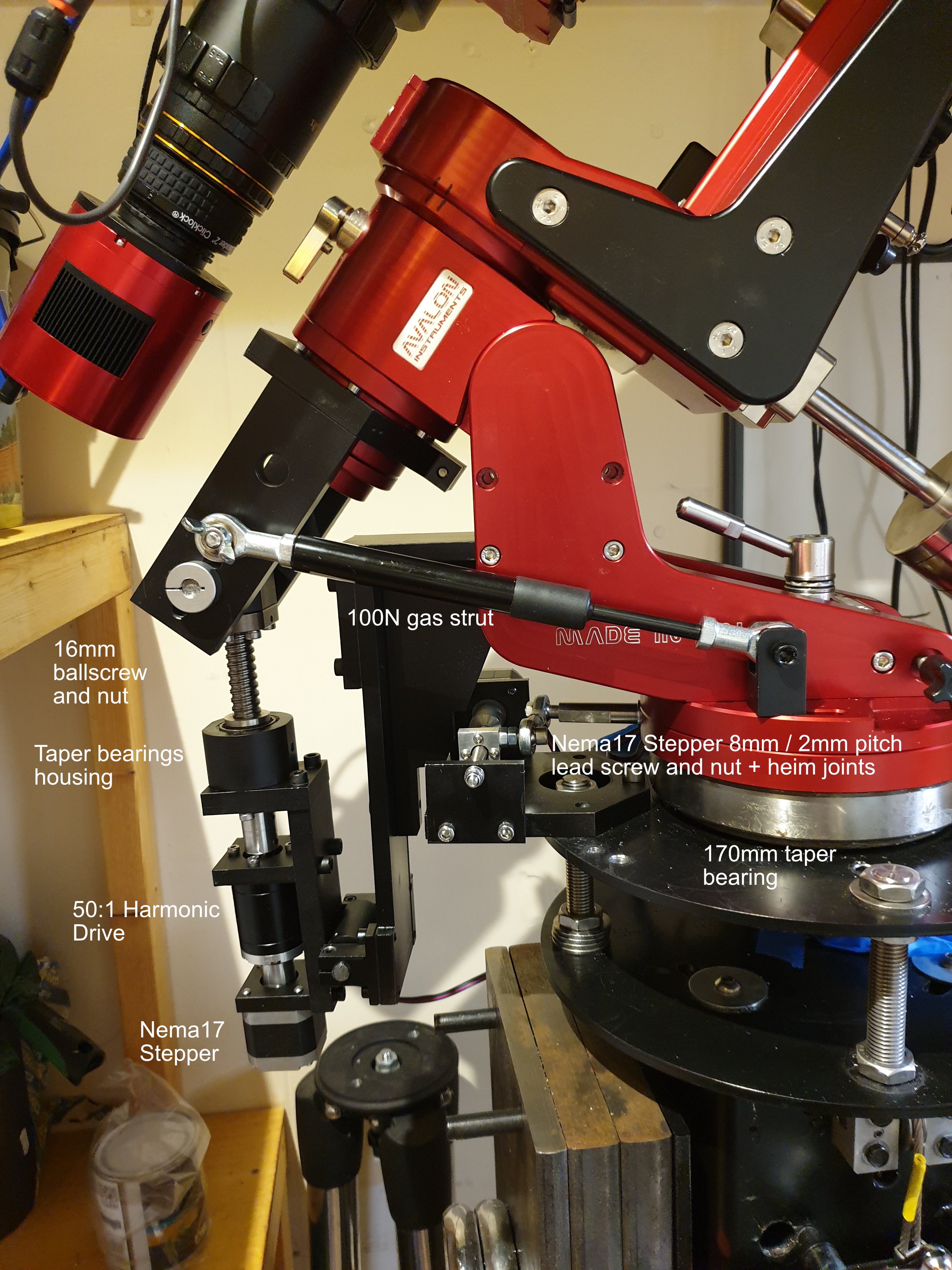
The final task is the one for the elevation which I am working on at the moment as it involves a 16mm ball screw and nut a 50:1 harmonic drive and a stepper + other machined parts and will then allow electronic control of the elevation adjustment as well once finished I will grab some images and add it to this thread. The current control is just using the Arduino ide to send serial commands to the nano and stepper drivers as l200 r200, etc and will add u??? d??? functionality later when the elevation is finished. Longer term will probably swap to an ESP32 linked to the Wi-Fi and MQTT broker so will then be able to use a web browser or my phone to connect via node red.
Cheers
Nick